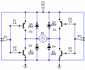
How the h-bridge circuit works. change the direction of rotation of the Bipolar transistor hbridge motor driver H bridge circuit diagram using transistor
Schematic diagram of a full H-bridge in a) OFF-state, b) Forward-state
H-bridges – the basics Discrete h-bridge circuit for enhanced vibration motor control Block diagram of the h-bridge amplifier including all driver stages
H bridge circuit
Simple h-bridge motor driver circuit circuits diy simple electronicBlock including H-bridge: working, circuits and applicationsSchematic circuit.
H-bridge transistor circuitMosfet h bridge [diagram] custom h bridge diagramMosfet h bridge.

Bridge motor circuit transistor dc bipolar driver hbridge control using transistors schematic peltier bjt arduino pwm robotroom current mosfet schematics
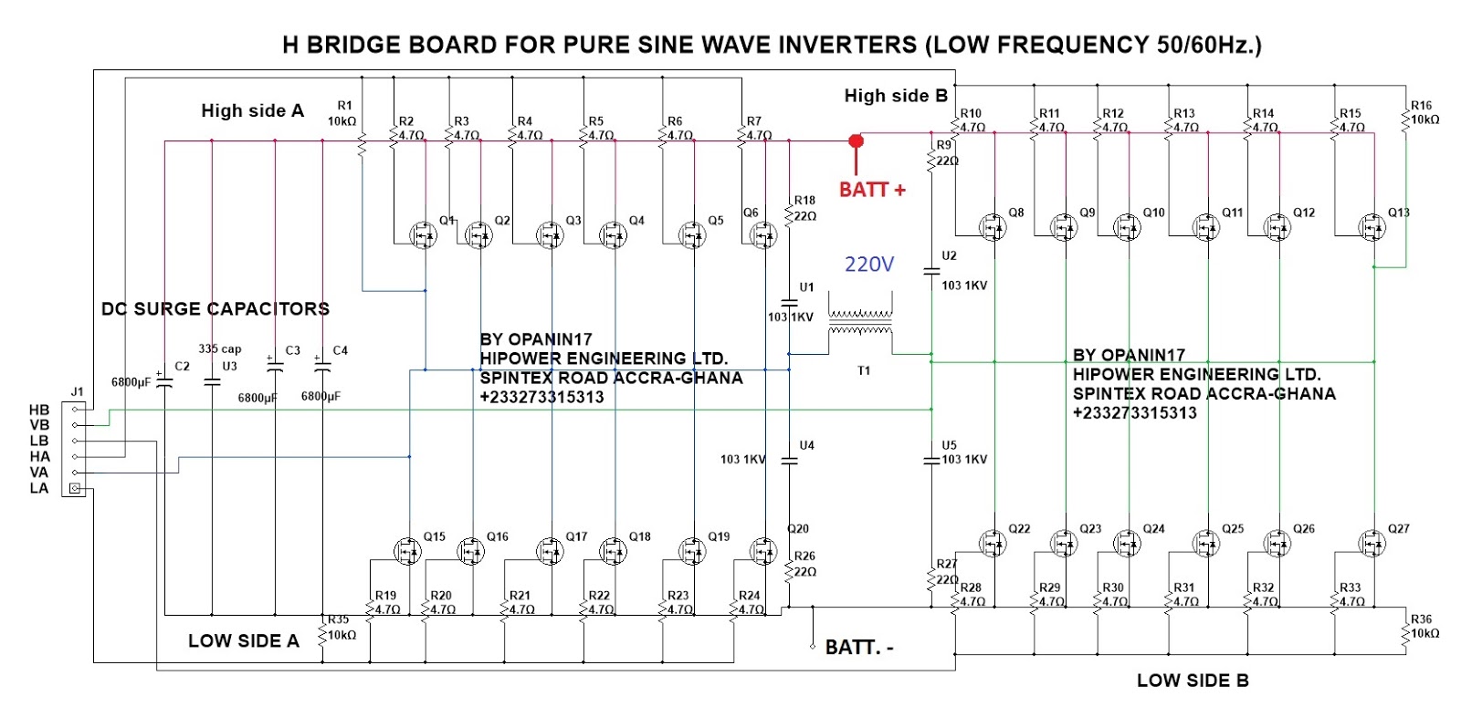
Solved the diagram below shows a typical h-bridgeBridge circuit diodes transistors motor using connecting relay high current not work mosfet transistor microcontroller pnp 5v use circuits devices H bridge inverter circuit design manual[diagram] h bridge inverter circuit diagrams.
Robotics bridges q3 q2 direction spinning backwards shaft start robotic turned happen energized gets instructables q1H-bridge inverter circuit diagram H bridge motor driver circuitMagiccode lesson 14: inbuilt motor controller.

Solved the diagram below shows a typical h-bridge
Circuits working explanation hacksterBridge circuit circuits schematic Driver circuits mosfet transistor pnp resistorsSchematic diagram of a full h-bridge in a) off-state, b) forward-state.
H-bridge circuit diagram.H bridge circuit diagram [diagram] h bridge inverter circuit diagrams[diagram] h bridge inverter circuit diagram.

Control system
H bridge schematic for motor controlBridge dc motor circuit control transistor How the h-bridge circuit works. change the direction of rotation of theBridge circuit driver click inverters.
Mpq6614-aec1 35v, h-bridge dc motor driver, aec-q100Circuit schematic of h-bridge. Many circuits: h bridgeDc motor control h-bridge circuit ~ gsmicro.

Solved 5. below is a partial illustration of the h-bridge
.
.


H-bridge: Working, Circuits and Applications - Utmel
H bridge circuit | Expert Circuits
![[DIAGRAM] H Bridge Inverter Circuit Diagram - MYDIAGRAM.ONLINE](https://1.bp.blogspot.com/-UTUmM1RiZGE/T59yEa-IzQI/AAAAAAAABOQ/Fm3VQim9Qik/s1600/How+to+Design+H-Bridge+Circuit.png)
[DIAGRAM] H Bridge Inverter Circuit Diagram - MYDIAGRAM.ONLINE

Bipolar Transistor HBridge Motor Driver - Robot Room

control system - Transfer function of an H bridge circuit - Electrical

H-bridge circuit diagram. | Download Scientific Diagram
Many circuits: H BRIDGE